EE3901/EE5901 Sensor Technologies Assignment 2 — Designing a capacitive sensor to measure water level
Introduction
A rough prototype of a water level sensor is shown in Figure 1. It is made from two pieces of aluminium foil that are sticky-taped to a glass beaker. Water has a high permittivity, so the presence or absence of water can be detected by changes in capacitance.
This device is easy and cheap to build and can be iterated on quickly. However, it suffers from several defects, as will be described below. Your task is to design an improved water level sensor. You will then build, test, and calibrate your design.
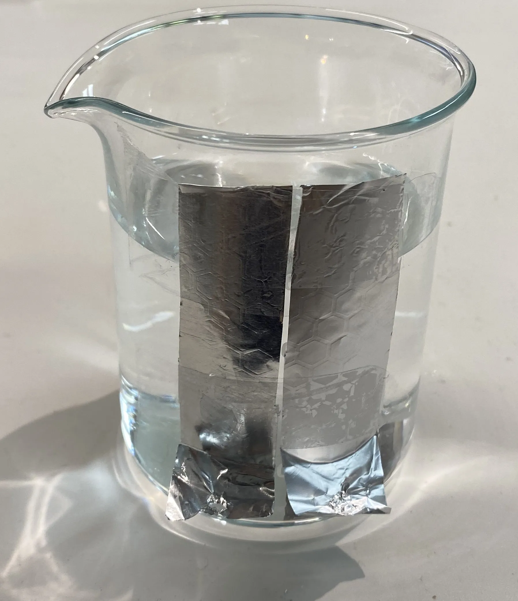
A prototype capacitive sensor made from readily available materials.
Zoom:Issues with this water level sensor
A good water level sensor would have the following properties:
- It should be independent of temperature. The permittivity of water has a strong temperature dependence, which interferes with the measurement.
- It should not suffer interference from nearby conductors or high permittivity objects.
Figure 2 shows the test results of using this sensor. It can be seen that the sensor does not meet these goals.
There is a temperature dependence, as shown by the difference between room temperature and chilled water cases. Note that cold water has a higher permittivity than warm water, so it makes sense that the capacitance would be higher.
The device is also subject to interference from nearby objects, such as a hand placed in the vicinity of the sensor.

Measured capacitance of the prototype sensor in Figure 1 under different conditions.
Zoom:Your task
Your task is to design, build, and test an improved water level sensor. Your sensor must be designed for a 200 mL lab beaker (like Figure 1). These are available in the workshop for you to use in development and testing.
You are free to use any sensor design, provided that the mechanism is capacitive and the sensor can be fabricated in the JCU engineering workshop. You may design your sensor to be placed on the outside of the container or be submerged in the liquid. If your sensor is submerged, then you must ensure that it is electrically isolated so that there is no conductive path through the liquid. (In practice, keeping the electrodes dry also helps avoid corrosion.)
You will be measuring your capacitance using an LCR meter. You are not required to design the interface electronics to connect your capacitor(s) to any downstream circuity. This assignment is limited to the design of the sensing element itself.
Recommended approach
It is suggested that you design your sensor to be made using aluminium tape on a plastic substrate. All the equipment of the workshop is available for your use. You can shape the plastic using the laser cutter, and then create conductive surfaces using aluminium tape. You can cut gaps between electrodes using a sharp knife along cuts you already made in the plastic. There are rigid and flexible plastics available for you to cut. A flexible plastic substrate can be shaped to the outside of the beaker.
You may also use 3D printing to make a plastic shape on which you affix conductive tape. You may also design your sensor as a printed circuit board and use the PCB milling machine.
The workshop staff will be busy be sure to discuss a suitable time frame for your work with them. Do not leave this task to the last minute.
Some design suggestions are as follows:
- There is a lot of useful information in this reference design from Texas Instruments. There are also good design guidelines from Analog Devices and Cypress. In general, you are not the first person to face this task, so take advantage of what information you can find.
- For external sensor designs, a ground plane behind the sensor will prevent interference from nearby objects. However, there will also be large mutual capacitances between the ground plane and each electrode, since they are essentially in a plane parallel geometry. This capacitance could be larger than the effect due to the water level. This is part of the design trade-off.
- For internal sensor designs, consider how you will keep the electrodes dry. These designs might be expected to be less robust and less suitable for hazardous/corrosive liquids.
Use a computer model for optimising your design
You must first develop a computational model to assist with your design, using the numerical methods discussed in lectures. Once you have a model, then you can vary certain aspects of the design and predict the resulting impact on the capacitance, and immunity to temperature variations and external impacts. In this way, you can quickly optimise your design. After you have developed your design on the computer, you must then fabricate it and test it experimentally. You are free to iterate as many times as you wish to obtain your final design.
Note the equation for the capacitance of a parallel plate capacitor (
Develop a calibration model
Your sensor will most likely consist of multiple pairs of electrodes. You must develop some mathematical equation where the measured capacitance(s) are entered as inputs, and the calculation result is the water level in the beaker. As a starting point, consider using linear regression to find the relationship between the capacitance and the water level. Naturally, you are free to use something else, if it results in better performance.
Oral presentation
You must prepare and deliver a presentation on your work. The time limit will be set by your lecturer. You must bring your design to show during the presentation, but you are not required to demonstrate it working. The following structure is recommended:
- Introduction
- Briefly describe the motivation and the problem that you are addressing.
- Literature Review [EE5901 students only]
- Review some aspect of the capacitive sensing literature and describe how this relates to your task. (See hints below).
- Computational modelling (This is likely to be your biggest section)
- Describe the testing you did on a computer, and what you learned. For example, if you trialled different sensor widths, show the results in your report and describe how you settled on the final design.
- Fabrication
- Describe how your device was built, and show some photograph(s) of it.
- Testing and calibration
- Show the results from testing your sensor.
- Describe how you developed a calibration model to convert these raw results into measurements of water level.
- Assess the accuracy of your overall system.
- Conclusion
- Summarise the project and give recommendations for future work (i.e. how could the system be improved, what else could be investigated, etc).
Literature review for EE5901 students
If you are enrolled in the Masters level version of this class, then you are required to engage more critically with the research in this field. In discussion with your lecturer, you should identify some aspect of capacitive sensing that interests you to investigate for a brief literature review.
Some possible topics:
- Methods of fabrication of capacitive sensors.
- Applications of capacitive sensing to wearables, healthcare, etc.
- Applications of capacitive sensing to robotics.
Your literature review should be relatively brief and focus on giving a survey of the field without going into all the technical details. Aim for 1-2 pages of text. The IEEE reference style is encouraged (but any format is acceptable so long as you use it consistently).
Your lecturer will be able to help you in formulating your review and critically analysing the research papers.
Submission
Prepare the following items for submission:
- Your presentation slides as a PDF.
- Your literature review as a PDF (EE5901 students only).
- Your software source code (e.g. as a Zip file containing all source code).
Submit your work via LearnJCU before the due date.
Assessment Rubric
For EE3901 students, the following rubric will be used for grading. For EE5901 students, this rubric will be used and assigned a weighting of 70%, with the literature review accounting for the remaining 30%.
| Criteria | HD (High Distinction) | D (Distinction) | C (Credit) | P (Pass) | F (Fail) |
|---|---|---|---|---|---|
| Computational Modelling (20%) | Develops an accurate and well-justified model to predict capacitance behavior. Validates predictions against known principles. | Model is mostly accurate, with minor omissions or assumptions. Predictions align well with expected behavior but lack full validation. | Model is functional but has notable flaws, such as incorrect assumptions or weak validation. Results are somewhat aligned with expectations but require further justification. | Model is functional but significantly flawed, leading to unreliable predictions. Justifications for modelling choices are weak or missing. | No computational model provided, or the model is completely incorrect. |
| Sensor Design Justification (30%) | Clearly explains how modelling results informed design choices. Addresses temperature dependence, external interference, and fabrication constraints with strong reasoning. | Justifies design choices based on modelling results, but some aspects lack depth. Considers key factors but does not fully address trade-offs. | Provides basic reasoning for design choices, but justification is weak or incomplete. Some important factors are overlooked. | Design is based on vague or incorrect reasoning, with little connection to modelling results. Key design considerations are missing. | No justification for design choices provided, or design is arbitrary with no rationale. |
| Fabrication and Build Quality (10%) | Sensor is well-constructed, follows the proposed design, and demonstrates excellent build quality. Fabrication techniques are well-documented. | Sensor is functional and mostly follows the proposed design, with minor flaws in construction. Documentation is mostly clear. | Sensor is built but has noticeable issues affecting performance. Fabrication process is poorly documented or lacks key details. | Sensor is incomplete or poorly assembled, significantly impacting functionality. Documentation is unclear or missing important steps. | No sensor fabricated, or the sensor does not function at all due to critical design/build errors. |
| Experimental Testing and Calibration (15%) | Conducts thorough testing and provides a well-documented calibration process. Data is analysed rigorously, and accuracy is assessed comprehensively. | Performs reasonable testing with mostly correct calibration. Analysis is good but lacks depth in identifying sources of error. | Testing is performed but lacks consistency or proper controls. Calibration is incomplete or poorly justified. | Minimal testing is conducted, and calibration is unreliable or missing. Little effort in analysing results. | No meaningful testing or calibration performed, or results are unusable. |
| Analysis of Results and Performance Evaluation (15%) | Provides a detailed and insightful analysis of sensor performance, including temperature effects, interference, and overall accuracy. Discusses limitations and potential improvements. | Analyses sensor performance well, covering most key aspects. Some discussion of limitations and possible improvements is included but lacks depth. | Basic analysis is provided but is missing key insights or overlooks important factors. Some discussion of limitations. | Analysis is presented but is minimal, lacking meaningful evaluation of performance. | No results analysis provided, or analysis is completely incorrect. |
| Presentation Quality (10%) | Presentation is well-structured, clear, and professional. All key aspects are covered with strong explanations and supporting visuals. | Presentation is well-organized and mostly clear but contains minor issues in clarity or structure. Some explanations could be stronger. | Presentation is mostly clear. Some sections are unclear, disorganized, or missing supporting visuals. | Presentation is somewhat clear but sections are poorly structured, difficult to follow, or missing key elements. Explanations are vague or incomplete. | No presentation submitted, or presentation is severely incomplete and unclear. |
General Grading Scale:
- High Distinction: Outstanding work, with a strong computational model, well-justified design, and thorough testing.
- Distinction: Good work, with a solid model and testing but minor gaps in justification or execution.
- Credit: Satisfactory work, with notable weaknesses in modelling, justification, or testing.
- Pass: Significant flaws in implementation or analysis, but some functionality is present.
- Fail: Incomplete or non-functional submission.