EE3901/EE5901 Sensor Technologies Practical 6 — Near-infrared spectroscopy
In this practical you will gain experience in analysing hyperspectral images.
Spectroscopy lab tour
Meet in the normal electronics lab. We will walk together to the JCU Rapid Assessment Unit (RAU) laboratory. You will be able to see the hyperspectral cameras and collect some data.
Software exercise
Returning to the electronics lab, you will now gain experience in analysing hyperspectral data.
The motivation for this activity is as follows. Olives are often sold in a form where the pit (the hard inedible seed) has been removed. However, the pit removal process is done mechanically and is not perfect. Occasionally a whole pit or a sharp fragment of a pit may be left behind. Olive producers would like to detect and remove these defects, but they are difficult to see with the naked eye. Hence, there is demand for alternative methods to detect pits and pit fragments. In this practical, you will explore the use of hyperspectral imaging to detect olive pits.
Data description
Click here to download the data for this practical (184 MB zip file).
Your training set is a single datacube containing 50 halved olives, of which 25 have a pit and another 25 do not. The training set is illustrated in Figure 1. You are also provided with a validation image as shown in Figure 2.
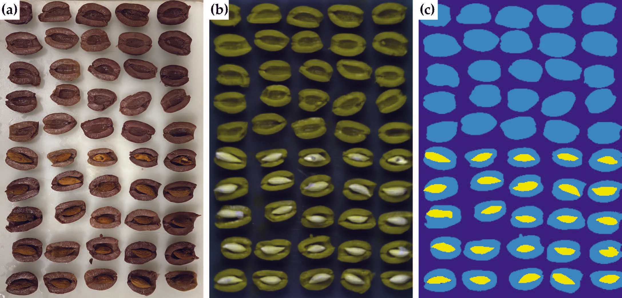
The training set for this practical. (a) True colour image of halved olives captured with an iPhone camera. (b) False colour image of the same plate extracted from the hyperspectral datacube. (c) Image labels, where yellow indicates the olive pits.
Zoom: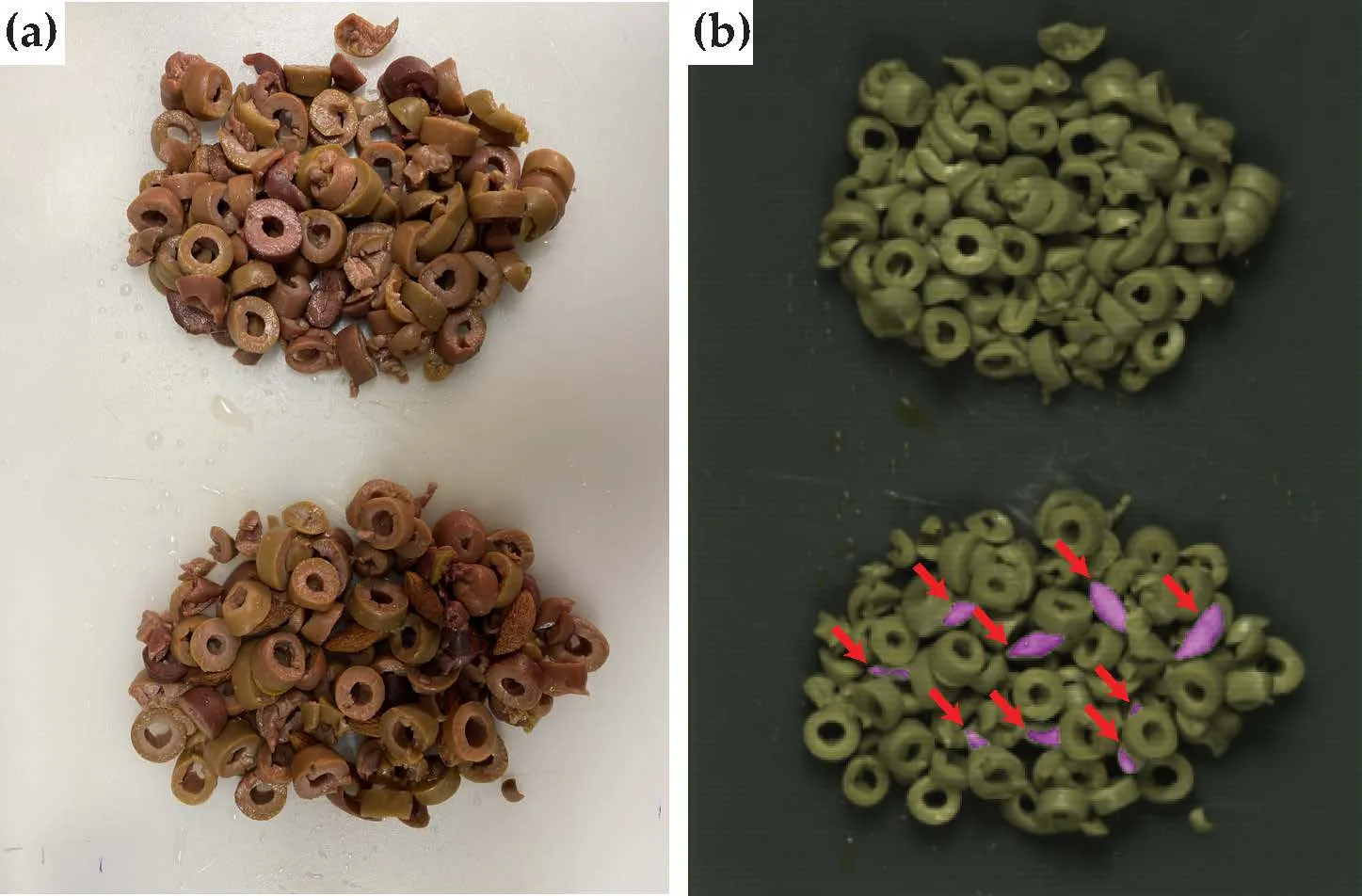
The validation image that you can use to test your model. (a) True colour image of two clumps of sliced olives. There are no pits in the top half of the image, whereas the bottom half has 8 pits intermixed with the olive slices. (b) False colour image where the pits are indicated with red arrows. These are automatic detections using a classification model similar to the one that you will develop in this practical. All 8 pits are detected, although one pit is detected twice since an olive slice obscures the middle of it.
Zoom:Your task
Your task is to train and briefly evaluate a classifier to detect olive pits. Your output should be in the form of a binary image, i.e. a black and white image where white indicates that a pit has been detected at that pixel.
Hints:
- This activity is an extension of the Week 11 tutorial, so it is highly recommended that you complete the tutorial before working on this practical.
- In these datacubes, the very top and bottom of the image show the metal camera stage. You should exclude those rows from your analysis. Basically you should tightly crop the images to the regions of interest. You can do this by indexing into the datacube to select specific rows, i.e. use Matlab code of the form
where n and m are the row numbers at which you wish to start and finish.reflectance = reflectance(n:m, :, :);
Assessment criteria
You will be awarded a binary mark (1 or 0) based upon completion of the task. To receive a mark of 1, you must demonstrate a working classifier that detects the pit fragments in the challenge image.
If you are not able to complete the task within the scheduled practical session, you have 7 days to complete the above items and submit evidence (screenshots, etc) by email to your lecturer.