All materials in that datasheet have tetragonal crystal symmetry, i.e. d31=d32 and d15=d24. The other piezoelectric constants that are not specified in the datasheet are zero.
Question 1
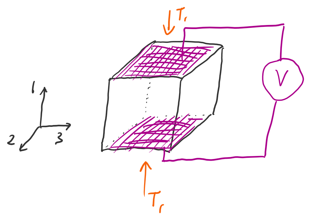
The material PIC153 from PI Ceramic GmbH is being used in a force sensing application,
as shown in Figure Q1. The material is poled along axis 3. The device is a 1 cm × 1 cm × 1 cm cube. Normal strains T1, T2 and T3 are applied as indicated. All shear strains are zero. Metal electrodes have been deposited onto the faces that lie in the 1-2 plane, allowing for voltage measurement V3 along axis 3.
Figure Q1:
The geometry of the device for Questions 1 and 2.
Zoom:
(a) Calculate the voltage V3 when T1=0, T2=0 and T3=1000N/m2.
(b) Calculate the voltage V3 when T1=0, T2=1000N/m2 and T3=0.
(c) Calculate the voltage V3 when T1=1000N/m2, T2=0 and T3=0.
(d) Determine the relationship between the stresses T1, T2 and T3 that will guarantee V3=0.
Answer
The electric displacement D is zero because the device is at open circuit conditions (no applied voltage). Hence the sensor equation is
Hence any values of T1, T2 and T3 that satisfy this equation will ensure zero voltage is measured.
Question 2
Ceramic piezoelectric materials lose their inherent polarisation if
they are heated above a temperature known as the Curie temperature.
Suppose that the sensor in Question 1 needs to operate at 300 °C.
Choose the material from the datasheet that will provide the highest
sensitivity to strains along axis 3 (as per Figure Q1)
but can tolerate these higher temperatures.
Answer
Sensitivity to strains along axis 3 are determined by d33. Out
of all the materials with a Curie temperature above 300 °C, the one
with the highest d33 is PIC255.
Question 3
A piezoelectric shear actuator is built using PIC151, as
shown in Figure Q3. The height of an individual layer (when it is perfectly vertical) is 0.8 mm. The applied voltage is V=100 V.
(a) Consider initially a device made from a single layer (of height 0.8 mm). Use the piezoelectric actuator equation
S=[d]TE+sT
to calculate the strain S on a single layer of the actuator. Assume no mechanical load (i.e. the stress is given by T=0).
(b) Now consider the multi-layer structure shown in Figure Q3 (b). Let n be the number of layers. Calculate ΔL, which is the distance travelled by the tip of the actuator when the voltage is varied from V=0 to V=100 V.
Hint: Engineering shear strain has units of radians, shown in the figure by the angle S5. You may approximate the geometry as that of a right-angled triangle.
(c) How many stacked actuator layers would be required to achieve a working range of 2 μm given an applied voltage range of 0 to 100 V?
Figure Q3:
A piezoelectric shear actuator. (a) A single element with the shear greatly exaggerated for clarity. Applying a voltage in direction 1 causes a bending of the tip. (b) A complete actuator has multiple layers with each subsequent layer having an opposite polarisation direction and opposite voltage polarity. The overall movement distance is nΔL
where n is the number of layers.
Zoom:
The only nonzero strain is the shear strain S5. Shear strain
S5 is a bending moment around axis 2. From the material datasheet,
d15=610×10−12 C/N. Note that the units C/N are equivalent
to m/V, so S5=d15E1 has no units (i.e. is measured in
radians).
Substituting the actual numbers, S5=7.6250×10⁻⁵ radians.
(b) Since the shear strain is small, we can approximate the geometry to be a triangle. Hence
ΔL=0.8mm×sinS5=61nm.
Note that shear strains are so small that sinS5≈S5,
so some references state the equation for travel distance as ΔL=LS5=d15V.
(c) Each actuator provides 61 nm of travel distance, so to achieve 2 μm
we need
n=61×10−92×10−6=33layers.
Question 4
A sample of quartz has a piezoelectric coefficient matrix of the form
Also, the material has a relative permittivity of 4.5.
(a) Sketch a 3D cube and draw the axes 1, 2, and 3 arbitrarily on your figure. Make sure that you use a right-handed coordinate system (i.e. use your right hand to determine
the polarity of each axis).
(b) You are designing a force sensor and want to maximise sensitivity to normal stresses. Choose two opposite faces of the cube to deposit metal electrodes. Indicate how you would connect a voltage meter in order to create a force sensor.
(c) Suppose your cube has dimensions 1 cm × 1 cm × 1 cm. Based on the geometry of part (b), you measure a voltage of 0.05 V. You know that the only stress acting on the quartz crystal is a normal stress along axis 1. Calculate the value of this stress.
Answer
(a-b) A sketch of the device is given in Figure A4.
Figure A4:
A quartz force sensor.
Zoom:
You could also have drawn your sketch with a different orientation.
To be correct the electrodes must connect to the faces whose normal
is along axis 1.
(c) Starting with the sensor equation (D=[d]T+ϵE=0)
and using the supplied values, we have